Oscillating hydrofoil for hydrokinetic power
Movie 1: Computational fluid dynamics simulation of an oscillating hydrofoil.
Movie 2: A two-foil device design with superimposed CFD.
Movie 3: Fish interacting with an oscillating foil.
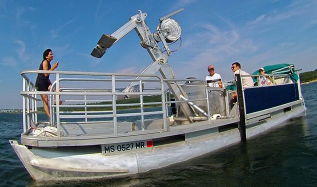
Picture 4: The 1 kW device on its pontoon test platform.
Movie 5: Two 1 kW devices mounted on a floating platform and tested in the Cape Cod Canal.
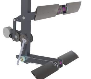
Rendering of the 1 kW device: foils on a vertical support, with the linkage that couples heaving to pitching.
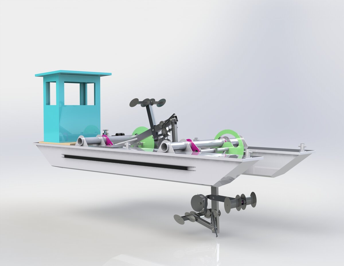
Rendering of a platform carrying two 1 kW devices in tandem.
Between 2013 and 2017 I led an ARPA-E programme at Brown University that took an oscillating hydrofoil for tidal and river power from the equations to 1 kW and 2 kW devices tested in the Taunton River and the Cape Cod Canal, which took it from technology readiness level 1 to 6. The physics is the lift a foil keeps after the flow separates from its leading edge, a cousin of the vortex-driven waving of marine grass; the engineering is a machine that turns it into power under both directions of the tide.
Energy from tidal, river flow, or ocean currents is a source of renewable energy we have not developed. The original grant was written in collaboration with Kenny Breuer and Heather Leslie, but Heather dropped out early on.
Hydrodynamics. The science behind oscillating hydrofoils is quite straightforward. Pitch the foil to the oncoming flow and let the water push the foil in the direction of the pitch. At the end of the stroke, reverse the pitch, the direction of the hydrodynamic force and hydrofoil motion. The adjoining movie 1 shows the kinematics and the fluid dynamics.
Most applications of airfoils and hydrofoils operate at low angles of attack where the flow remains attached. Our oscillating hydrofoils for power generation work at high angles of attack. Even after the flow separates from the leading edge, the hydrodynamic lift is quite high for quite some time until the leading-edge vortex forms and is shed. It is this lift that the oscillating foil uses to drive its motion. As a result, for the same amount of power, the foil moves quite slowly – peak velocity less than freestream. See this paper for more details..
Furthermore, these devices can be used in tandem. The vortices shed by an upstream foil interact constructively with a downstream oscillating foil. These two features formed the basis of the technology translation.
Device design. The Leading Edge Oscillating Hydrofoil (as we call it), consisted of two coupled foils oscillating 90 degrees out of phase to get over the dead spot at the end of a foil’s stroke (just like a two-stroke IC engine). The pitch is mechanically linked to the heave and over the whole stroke is power neutral. A generator (the cylindrical shape on the left) converts the motion into electricity. A small onboard processor controlled the oscillation frequency by varying the generator load. The device worked under bidirectional flow.
Fish friendliness. In collaboration with Prof. Dave Ellerby, Wellesley College, we also studied the interaction between a species of fish and oscillating foils in the lab flume. The fish cortisol level showed negligible change when introduced to the oscillating foil, consistent with an independent DOT/ARPA-E assessment of the technology’s environmental effects.
Field testing. A 1 kW device was tested on a floating platform in the Taunton River, and a 2 kW device subsequently in the Cape Cod Canal. Two 1 kW foils were also operated in tandem on a single platform. The downstream foil intersects the vortex wake of the upstream foil and suffers less performance loss than a rotor in the equivalent position, which indicates that such devices may be spaced more closely than rotor-based arrays.
Tech transfer. Michael Miller, then a PhD student at Brown with me, Thorne Sparkman of the Slater Tech Funds and I participated in an NSF I-Corps program, and undertook a survey of the industry ecosystem surrounding hydrokinetic power. A techno-economic analysis was developed by Gus Simiao. However, we concluded that while the technology performs as expected, market forces are not suitable for commercialization yet. The greatest factor was climate change, which could sometimes even run the river dry. Investment was tricky due to the uncertainty it introduced.
Funding. The work was carried out at Brown University between 2013 and 2017 under an award of approximately $3.5 million from the Advanced Research Projects Agency-Energy, on which I was the principal investigator with Kenneth Breuer and Heather Leslie as co-investigators. It was one of 66 projects selected under ARPA-E’s OPEN 2012 programme, which distributed $130 million in total.
Outreach. The project was featured on the front page of the Providence Journal, and was the only one at the time in the state of Rhode Island. In February 2014, a team led by me presented our early results at the ARPA-E Energy Innovation Summit in Washington, and to the Bicameral Task Force on Climate Change convened by Senator Sheldon Whitehouse and Representative Henry Waxman.
People. Michael Miller, whose doctoral thesis is on this device, and Jennifer Cardona ran the field campaign. Jennifer Franck, Benjamin Strom, Daegyoum Kim and Niall Mangan contributed to the fluid mechanics, and Thomas Derecktor and Steven Winckler to the engineering and commercialisation. A dozen undergraduate and graduate students worked on the experiments. Alice Fawzi served as the project manager with remarkable efficiency.
Publications
Energy harvesting performance and flow structure of an oscillating hydrofoil with finite span
Kim, Strom, Mandre, Breuer. J. Fluids Struct. 70, 314-326 (2017).PDF Publisher link
Abstract: The energy harvesting performance and resulting flow structures of a hydrofoil oscillating in pitch and heave are studied experimentally in a water flume. The shape of a hydrofoil cross-section is shown to have negligible influence on the power generation for the geometries tested. It is found that contribution to efficiency from heaving motion increases with reduced frequency at optimal pitching amplitude. However, contribution to efficiency from pitching motion decreases with reduced frequency because the development of a leading-edge vortex during the stroke is delayed at the high reduced frequency. … (read more)
Confinement effects on energy harvesting by a heaving and pitching hydrofoil
Su, Miller, Mandre and Breuer. J. Fluids Struct. 84, 233-242 (2019).PDF Publisher link
Abstract: Wall confinement effects on the energy harvesting performance by a flapping hydrofoil (aspect ratio 4.5) have been investigated in a circulating water flume at a Reynolds number of 50,000. Measurements of hydrodynamic forces are taken for three different confinement configurations (unconfined, one-wall and two-wall confinement) and a series of confinement levels for each configuration. Compared with the unconfined situation, a significant improvement of efficiency performance is obtained for strong two-wall confinement due to the enhancement of the hydrodynamic forces, while only a modest increase is observed in the one-wall confinement configuration. … (read more)
In the press
- Rhode Island Public Radio · Capturing a river's energy with wings
- The Providence Journal · On the Taunton river, Brown researchers pursuing future of tidal energy
- The Providence Journal · Brown University engineers design unique device that could harness power of tides
- News from Brown · A better water wing to harvest tidal energy
Other things we work on
- Feet and fins
- Fluid mechanical kinematic optimization
- Flowing soap films
- Waving marine grass
- Cheerios effect
Interested in working on this? Funding schemes I can supervise or host are listed with their deadlines, and the people who have worked on it are here.